Click any picture for
enlargement.
Research
There's a lot of construction activity these days. I could see several
building projects on my commute to work, without going out of my way.
Those sites gave me ideas
about the visible components of contemporary
construction. I used search engines to explore construction projects
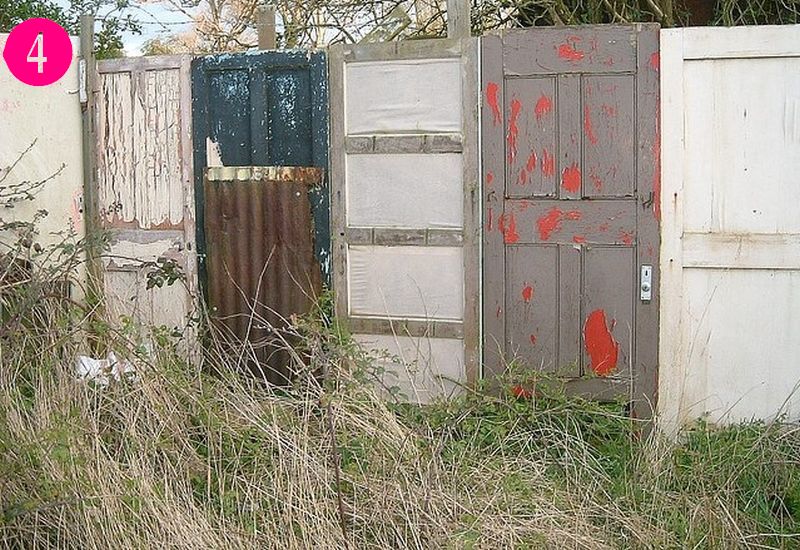
from the 1950s, but the most striking aspect came from my memory. I
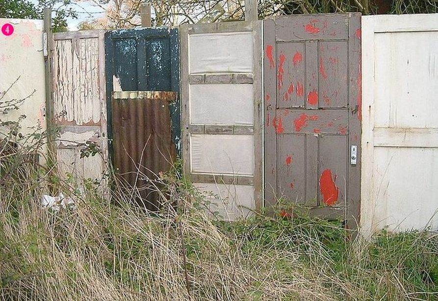
have a vivid memory that construction sites used old doors to make a
wall around the site. I think I remember peeking through keyholes to
look at what was going on inside.
I Googled "fence made of
doors" and found several examples ④
that confirmed my memory. The
pictures gave me some ideas what such a wall would look like. I
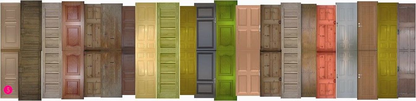
continued Googling individual old doors and collected images of all
that I liked.
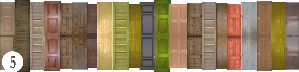
I lined up all the doors to
get a head-on (perpendicular) view ⑤. I used
PowerPoint, but I'm sure
that
drawing programs would also work.
Wall
of Doors
Constructing the wall of doors posed a problem: what material could I
use that would be visible from both sides and wouldn't be too thick?
Fortunately, I had used aluminum trim coil for backdrops and had
sufficient cut-offs for this project. The trim coil is 0.021 inches
thick, which works out to 1.8 scale inches thick in HO. That was a
pretty good thickness for my doors.
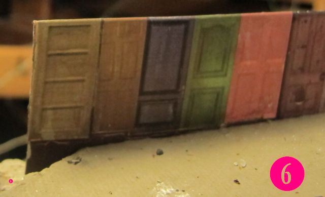
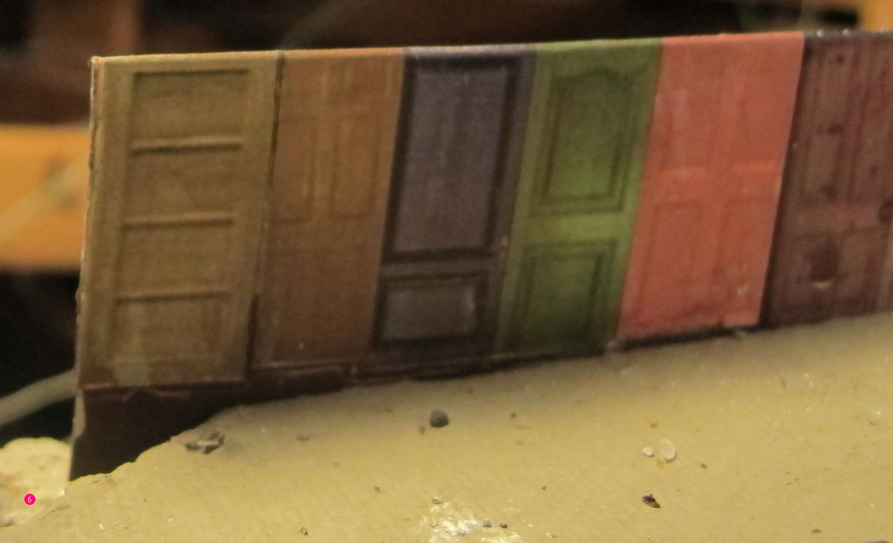
In PowerPoint,
I flipped the image along the top edge. I positioned the original and
flipped image so that I could paste both sides of the wall of doors to
the trim coil. I used a glue stick to attach the images to the trim
coil. That also accomplished having a finished top edge, which changed
color from door-to-door ⑥. The height was cut
so there was enough
aluminum to attach to the sides of the opening.
The Homasote sub-roadbed usually didn't align with the plywood
substrate, so the aluminum wall was cut so there was about a half-inch
for attachment. I nailed the aluminum to the edge of the Homasote. The
bottom edge of the doors should align with the surface of the
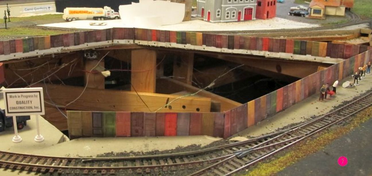
Homasote. I cut the aluminum so that it was exactly the
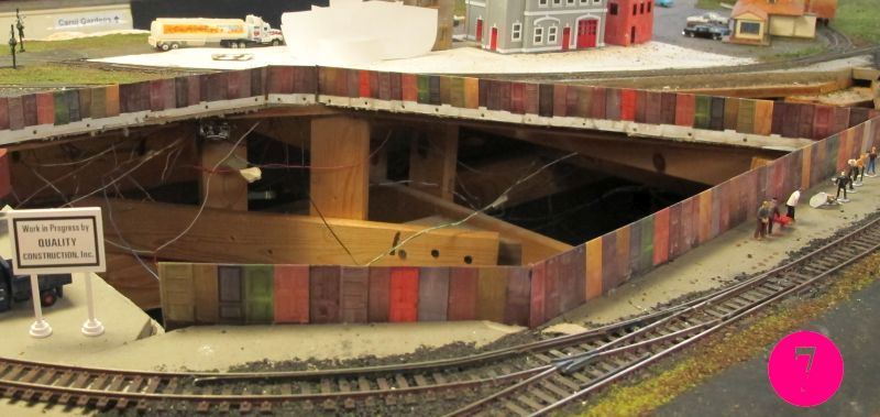
length of each side of the construction. Figure ⑦
shows doors installed
on three
sides of the hole. One wall was modeled as a chain-link fence so that
the construction crew could have a clear view of the site.
It's obvious from these pictures that the wall of doors is the edge of
the opening. But we want the illusion that the ground continues past
the wall a few scale feet until the edge of the excavation is reached.
That illusion is created when we add the ground after the separate
construction is inserted.
Retaining Walls—Shoring
Another
important detail is the "retaining wall" around the excavation.
This wall keeps the earth from tumbling into the excavation. I learned
that "shoring" was the proper term for these "retaining walls" and that
the style I was interested in modeling was "soldier pile shoring."
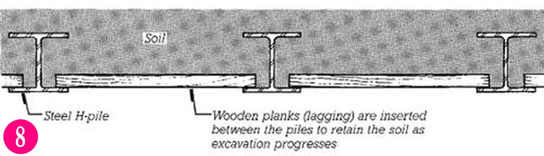
Soldier pile shoring is an assembly of vertically oriented steel
H-beams placed every six to eight feet on center in a straight line,
referred to as piles. (The Soldier beams are called H-beams, rather
than I-beams, because the flange is much wider. In cross-section, the
H-beam looks like the letter H on its side, while an I-beam looks like
an upright letter I.)
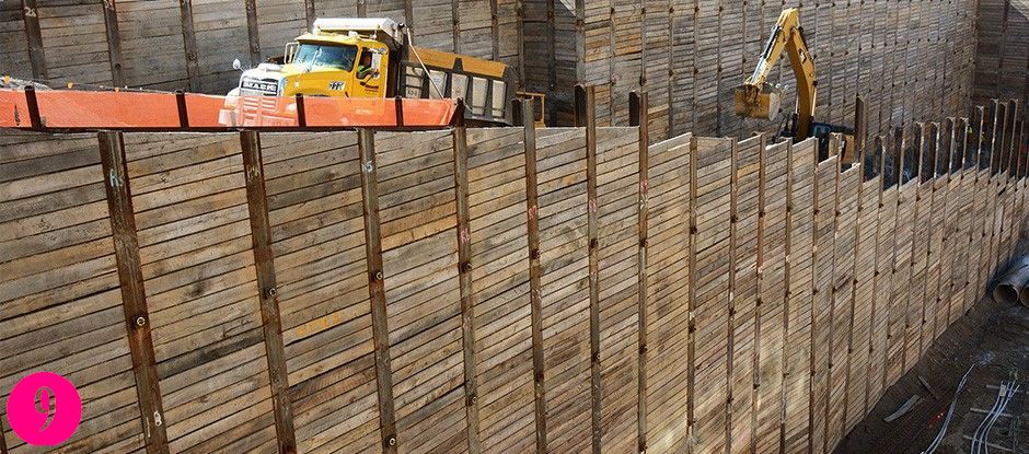
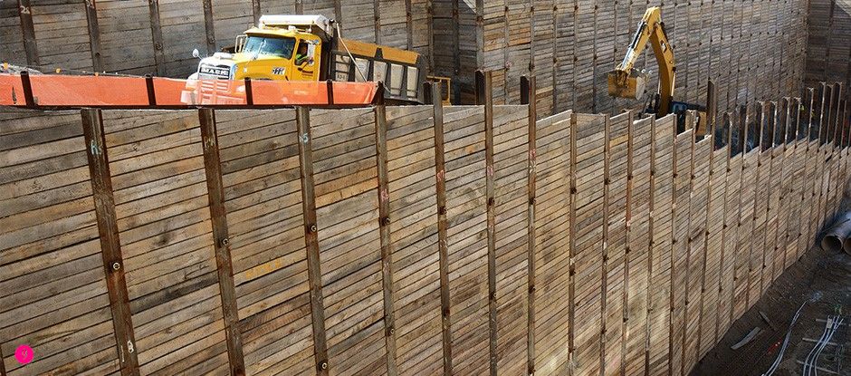
Wood boards, referred to as lagging, span
horizontally from one wide flange to the next and the entire assembly
holds back earth on one side allowing a vertical cut on the other.
Pairs of soldier beams are driven to a depth slightly below the final
excavation. The lagging timber, which is slightly shorter than the
spacing but on the order of 2 to 4 inches thick, are installed behind
the front flange to retain the soil as excavation proceeds
⑧.
I used the picture of a prototype construction site as inspiration
⑨.
It isn't feasible to construct model soldier pile shoring following
prototype construction methods. I had to come up with a different
technique. I used Evergreen Scale Models (plastic) H-Columns .125" part
# 284, retail 3 / $3.59. To represent the lagging, I used basswood
scribed sheets from Mt. Albert, MA723P12, 2 pieces 1/16" thick x 4" x
12", 0.125" = 1/8" scribe.
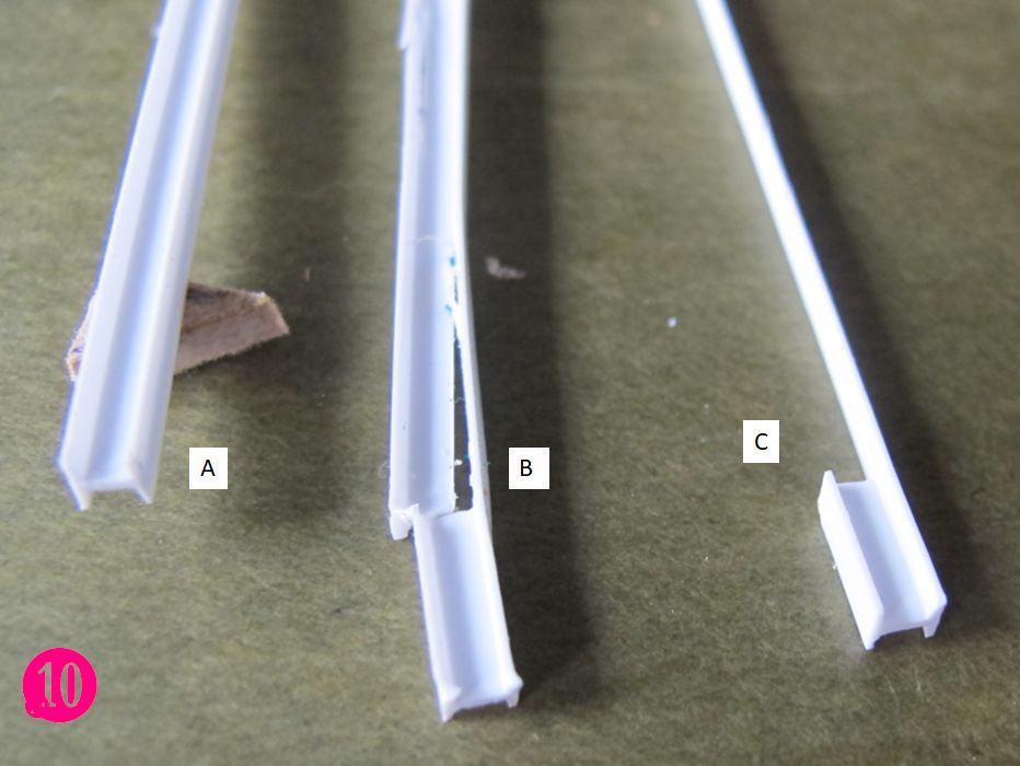
I reversed the roles of the lagging and
columns. The basswood sheets provide the structural integrity and the
plastic simulates the steel columns. The general idea is to show enough
of an H-column at the top of the lagging to convince the viewer that
the column continues all the way down, when in fact most of the
H-column has been cut away and only the surface flange remains. I call
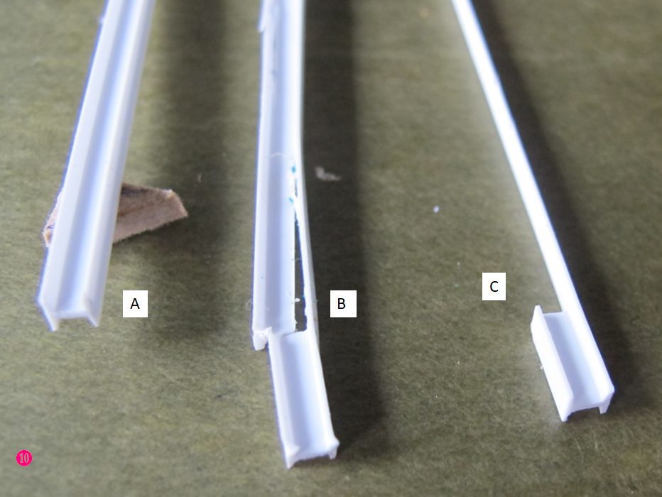
these "false-top H-columns." Picture
⑩ shows an
unmutilated
H-column
(A), a column where only a half-inch of H retains the T-shaped part is
partially cut away (B), and the resulting H-top and flat false-front
when the T part is completely removed (C).
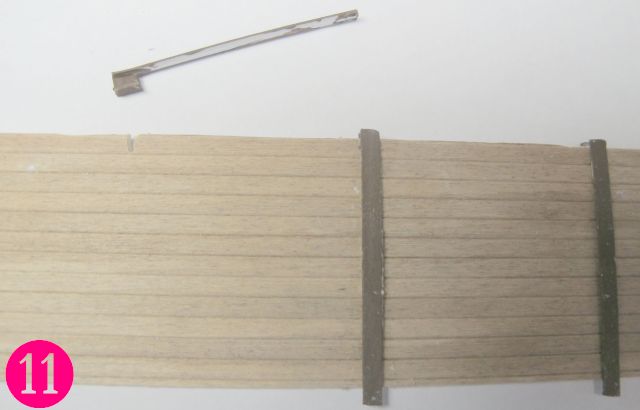
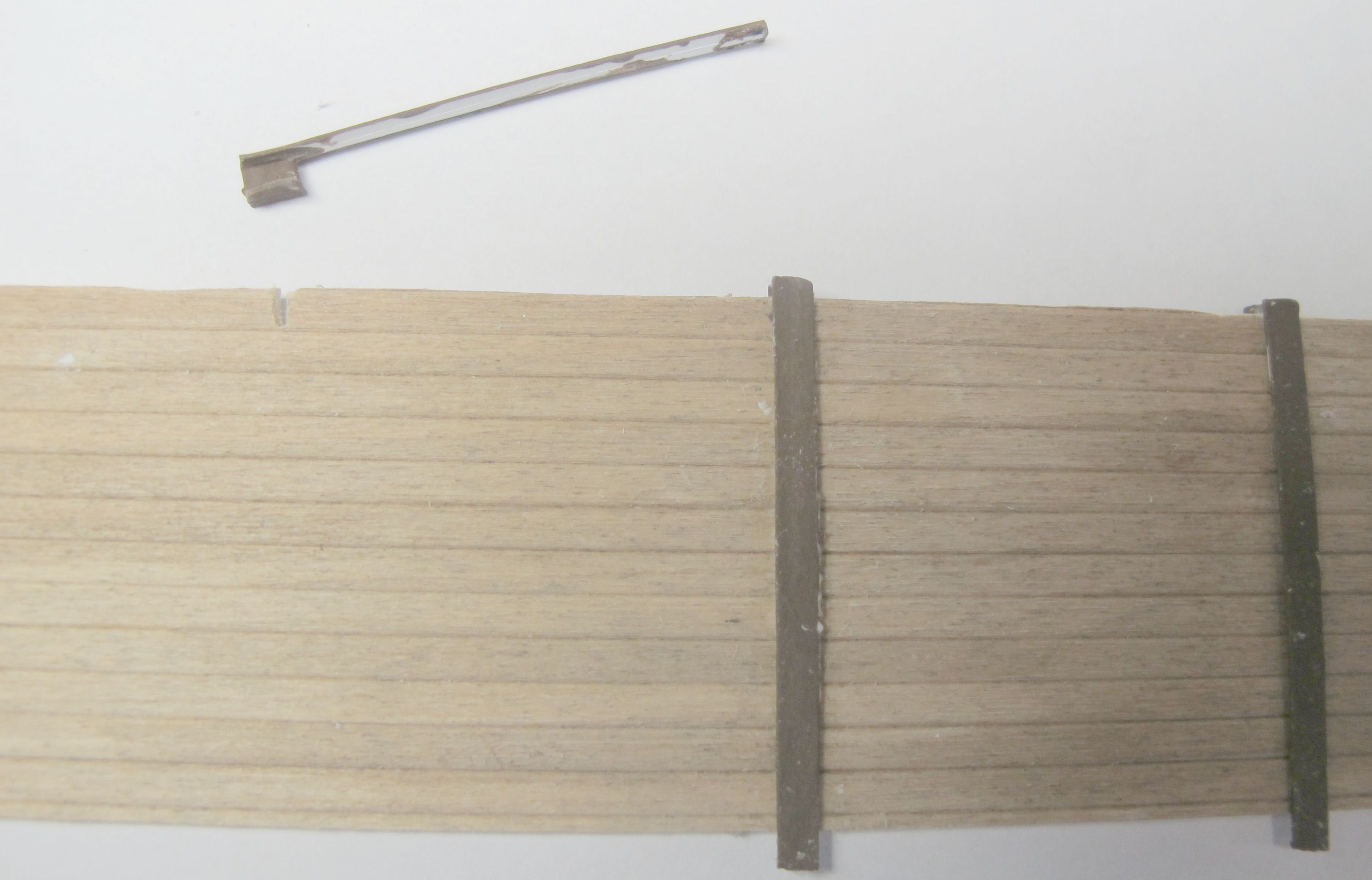
Picture
⑪ shows
a notch
cut into the top board of the basswood, into which the stub H-column is
inserted. When the basswood is put in place, only the top of the
H-column is visible. The viewer believes that the flat part of the
column down the front of the basswood lagging has the rest of the H
hidden by the earth it is holding back. The columns have been painted
oxide brown.
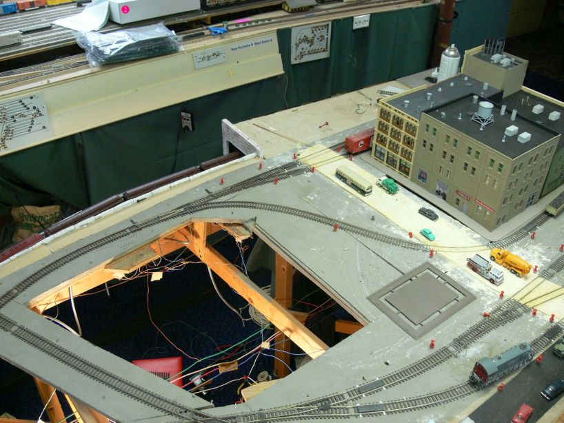
Building
in A Box
Modelling the construction site in the layout was never considered. It
was destined to be built away from the layout and installed when ready.
I made a box to fit the opening
③. As
you see, the box was
built from a repurposed appliance container; I think it was a
microwave.
The
box had to be odd shaped to fit the opening.
Unfortunately, a switch machine mount had intruded into the opening
space, which I had to work around. I also had to provide a base in the
benchwork to support the box. When I first made the box, the sides were
higher than the surrounding ground level, but that got trimmed away.
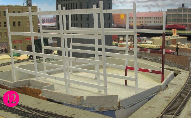
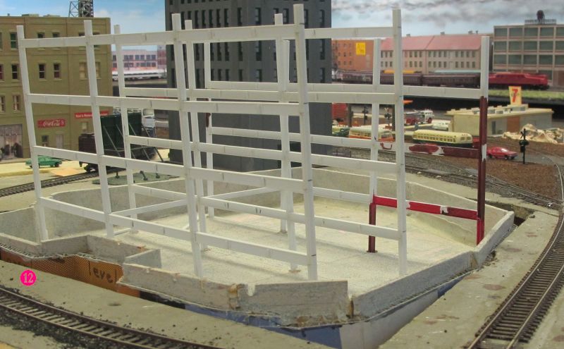
Picture
⑫ shows the project inserted in
the layout for a test
fit. A few beams
have been painted; but lagging has not been installed. Compare this
view with when painting and lagging are complete. In this view soil has
been added inside the retaining walls.
shows how the soil inside and outside the fence completely obliterates
the out-of-site construction.
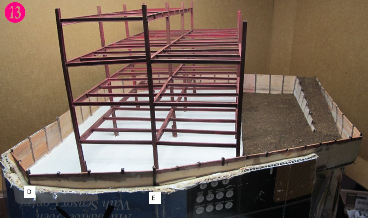
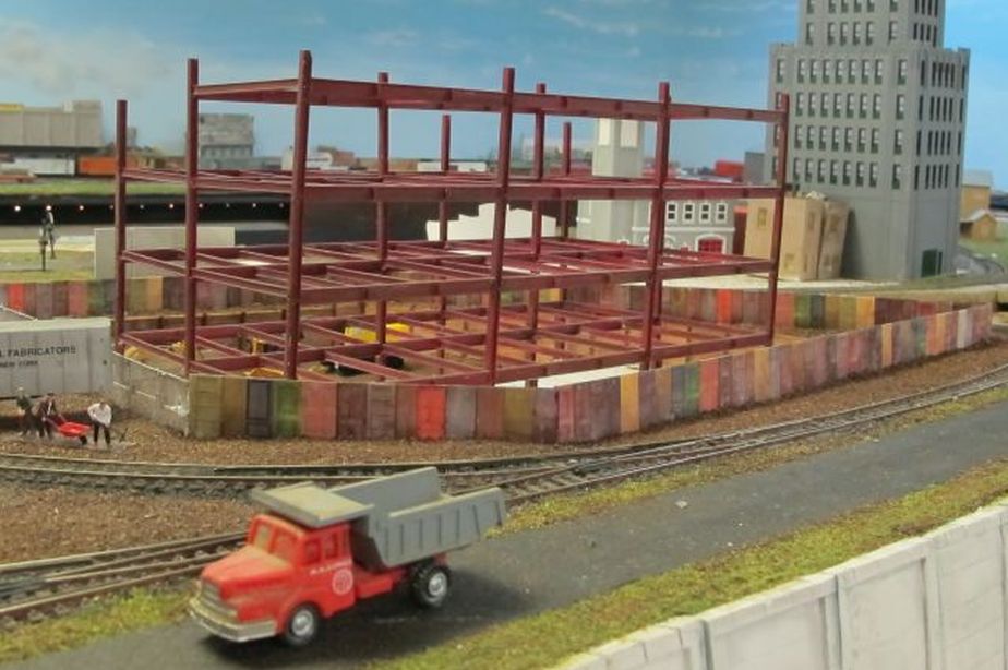
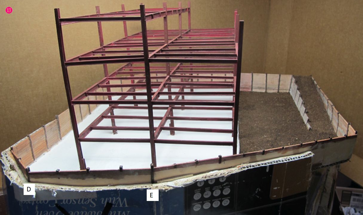
Picture
⑬ shows the project ready to insert in
the layout.
This picture was taken after the steel was painted and plaster was
poured to simulate the concrete foundation. Also notice the back of the
retaining wall. H-columns are used to join pieces of basswood (D and
E), while the backs of the false-top H-columns can be seen to go down
only a short distance. In this view soil has been added inside the
retaining walls.
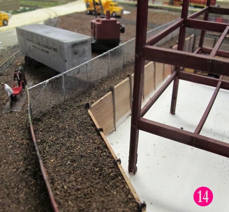
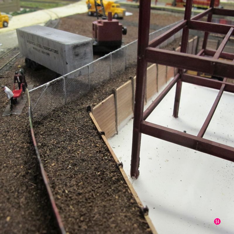
The illusion is complete when soil is added outside the lagging.
Picture
⑭ shows how the soil inside and outside
the fence
completely obliterates the out-of-site construction.
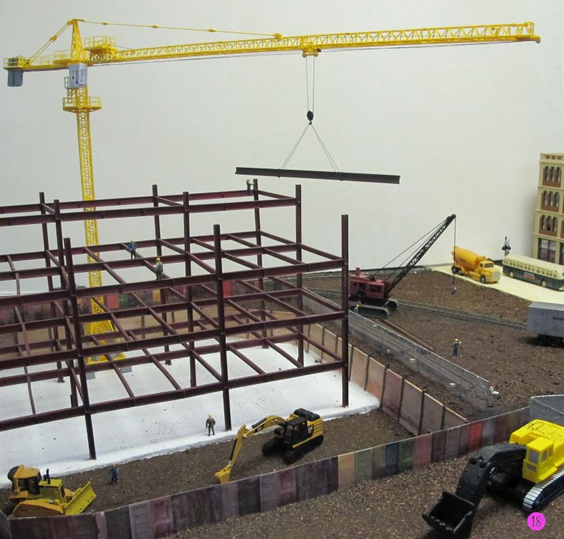
Crane
Tower, or hamerhead, cranes mark all major construction sites. They
arrive at the
construction si
Return
to top te on 10 to
12 tractor-trailer rigs. The crew uses a
mobile crane to assemble the jib and the machinery section, and places
these horizontal members on a 40-foot (12-m) mast that consists of two
mast sections. The mobile crane then adds the counterweights. The mast
rises from this firm foundation. The mast is a large,
triangulated lattice structure, typically 10 feet (3.2 meters) square.
The triangulated structure gives the mast the strength to remain
upright. To rise to its maximum height, the crane grows itself one mast
section
at a time! The crew uses a top climber or climbing frame that fits
between the slewing unit and the top of the mast.
The design of hammerhead crane evolved first in Germany
around the turn
of the 19th century, The "hammerhead", or giant cantilever, crane is a
fixed-jib crane consisting of a steel-braced tower on which revolves a
large, horizontal, double cantilever; the forward part of this
cantilever or jib carries the lifting trolley, the jib is extended
backwards in order to form a support for the machinery and
counterbalancing weight.
In addition to the motions of lifting and
revolving, there is provided a so-called "racking" motion, by which the
lifting trolley, with the load suspended, can be moved in and out along
the jib without altering the level of the load. Such horizontal
movement of the load is a marked feature of later crane design.
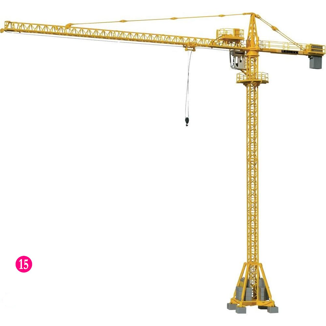
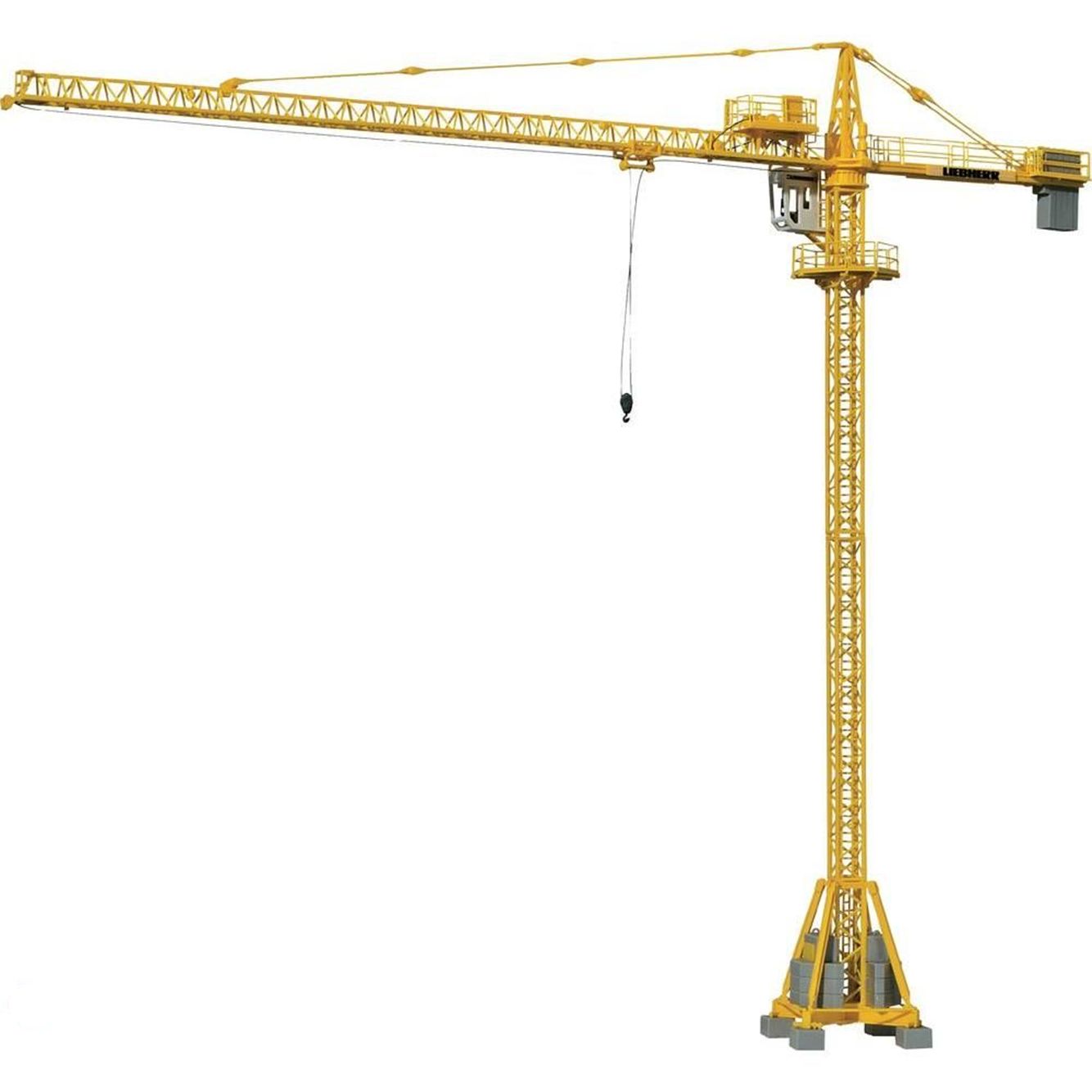
Kibri offers a plastic kit of a yellow
Construction Crane # 10202
⑮,
which appears prototypical of tower cranes I’ve seen on construction
sites. The kit consists of twelve unique sprues, some of which are
duplicated. All the sprues are illustrated on one A4 sheet, with each
part number shown. There are eighteen assembly steps, each separately
illustrated, showing how the parts fit together. These illustrations
are 99% wordless. The part numbers are shown; you have to tediously
search the sprue illustration to find which sprue the parts are on. At
the end of the assembly process, the crane does indeed look like the
illustration.
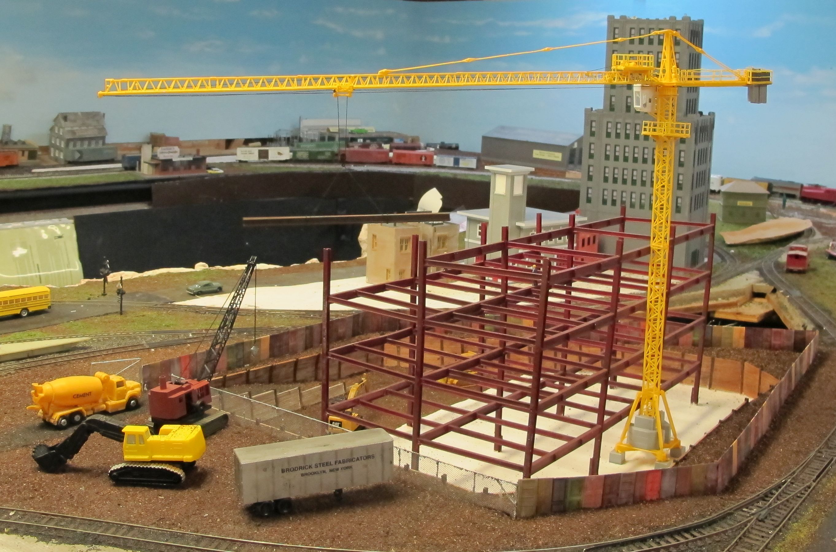
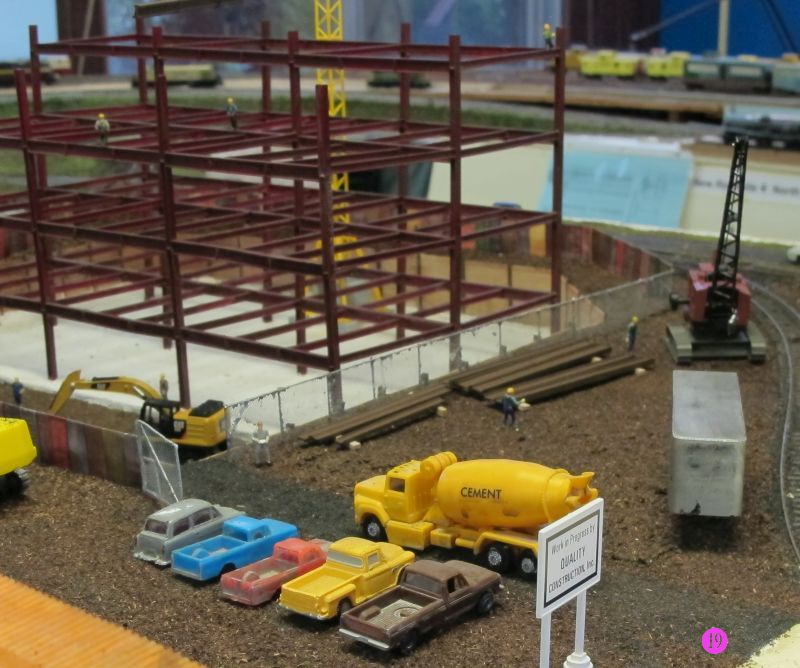
Finished
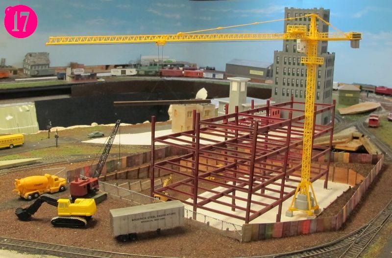
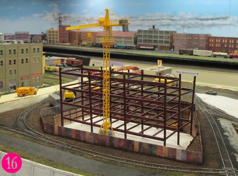
The next step was to dress the scene. People always add to a
scene. I
added eight construction workers. Picture
S
shows one perspective. You may find it easier to spot them in T.
Beams are laid on 8 foot
wood 4 x 4s, ready to be picked up by the tower crane.The 2
hook-on ironworkers are standing by the stacked steel. The steel has
been delivered by rail and shaken-out on the wood by the brown crawler
crane. The foreman is standing by the gate with a sequence of beams in
hand. Two workers are standing on ground level near the backhoe and
tractor. The connectors, ironworkers, are standing on the beams waiting
for the crane to deliver the next piece of steel. One workers is
bolting up the column connection in the far right corner!

 Vienna
was built using
L-girder benchwork, risers, and subroadbed plywood stringers, many of
which came from a sheet of .5" plywood using a sabre saw cookie-cutter
operation ①. As shown, this left several large
gaps, or holes, for
future
imaginative scenicing ②. I decided to
build a new headquarters
building for the Abrams Railroad Empire.
Vienna
was built using
L-girder benchwork, risers, and subroadbed plywood stringers, many of
which came from a sheet of .5" plywood using a sabre saw cookie-cutter
operation ①. As shown, this left several large
gaps, or holes, for
future
imaginative scenicing ②. I decided to
build a new headquarters
building for the Abrams Railroad Empire.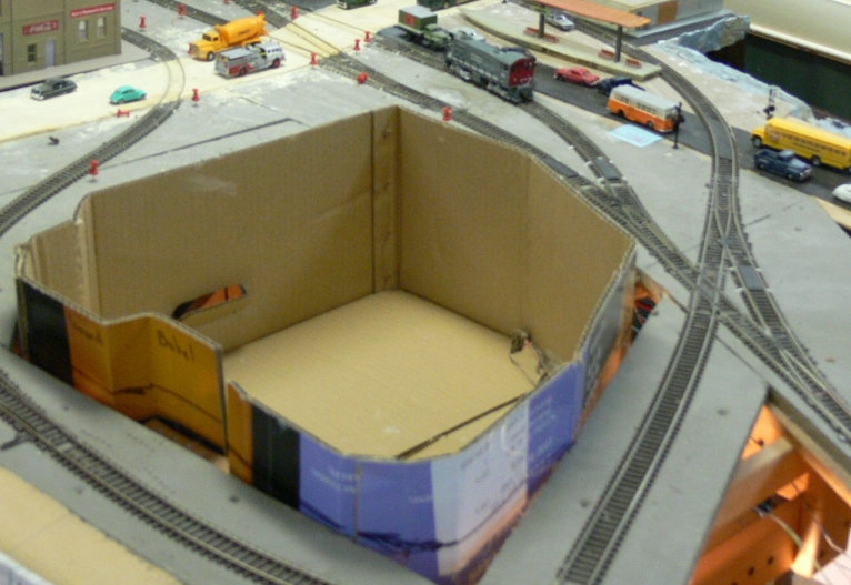
 There's a lot of construction activity these days. I could see several
building projects on my commute to work, without going out of my way.
There's a lot of construction activity these days. I could see several
building projects on my commute to work, without going out of my way.

 Wood boards, referred to as lagging, span
horizontally from one wide flange to the next and the entire assembly
holds back earth on one side allowing a vertical cut on the other.
Pairs of soldier beams are driven to a depth slightly below the final
excavation. The lagging timber, which is slightly shorter than the
spacing but on the order of 2 to 4 inches thick, are installed behind
the front flange to retain the soil as excavation proceeds ⑧.
I used the picture of a prototype construction site as inspiration ⑨.
Wood boards, referred to as lagging, span
horizontally from one wide flange to the next and the entire assembly
holds back earth on one side allowing a vertical cut on the other.
Pairs of soldier beams are driven to a depth slightly below the final
excavation. The lagging timber, which is slightly shorter than the
spacing but on the order of 2 to 4 inches thick, are installed behind
the front flange to retain the soil as excavation proceeds ⑧.
I used the picture of a prototype construction site as inspiration ⑨.
 Picture ⑪ shows
a notch
cut into the top board of the basswood, into which the stub H-column is
inserted. When the basswood is put in place, only the top of the
H-column is visible. The viewer believes that the flat part of the
column down the front of the basswood lagging has the rest of the H
hidden by the earth it is holding back. The columns have been painted
oxide brown.
Picture ⑪ shows
a notch
cut into the top board of the basswood, into which the stub H-column is
inserted. When the basswood is put in place, only the top of the
H-column is visible. The viewer believes that the flat part of the
column down the front of the basswood lagging has the rest of the H
hidden by the earth it is holding back. The columns have been painted
oxide brown.
 Tower, or hamerhead, cranes mark all major construction sites. They
arrive at the
construction siReturn
to top te on 10 to
12 tractor-trailer rigs. The crew uses a
mobile crane to assemble the jib and the machinery section, and places
these horizontal members on a 40-foot (12-m) mast that consists of two
mast sections. The mobile crane then adds the counterweights. The mast
rises from this firm foundation. The mast is a large,
triangulated lattice structure, typically 10 feet (3.2 meters) square.
The triangulated structure gives the mast the strength to remain
upright. To rise to its maximum height, the crane grows itself one mast
section
at a time! The crew uses a top climber or climbing frame that fits
between the slewing unit and the top of the mast.
Tower, or hamerhead, cranes mark all major construction sites. They
arrive at the
construction siReturn
to top te on 10 to
12 tractor-trailer rigs. The crew uses a
mobile crane to assemble the jib and the machinery section, and places
these horizontal members on a 40-foot (12-m) mast that consists of two
mast sections. The mobile crane then adds the counterweights. The mast
rises from this firm foundation. The mast is a large,
triangulated lattice structure, typically 10 feet (3.2 meters) square.
The triangulated structure gives the mast the strength to remain
upright. To rise to its maximum height, the crane grows itself one mast
section
at a time! The crew uses a top climber or climbing frame that fits
between the slewing unit and the top of the mast.