|
Crossing Gates | |
|
Research
& Selection
I started by researching what products were commercially available. I like searching on the Internet and I usually find products I didn't know existed, product reviews, and all kinds of related information. My initial question was whether I could buy a complete system or would I have to assemble sub-systems from different manufacturers? Cost was also a consideration. |
|||
I
found that MTH offers a motorized HO operating crossing gate
equipped with sound, flashing LEDs and eight optical sensors [note 1].
This package includes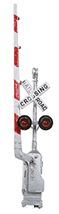 everything needed: two masts with interchangeable
short and long barricade arms, metal setup template, speaker with
enclosure, master and slave motor enclosures, signs, and wires. The MTH
user manual was on-line [2] .There was a caution about the amount of
space required under the layout. I hadn't given this a lot of thought
previously. Upon examination, I determined that I didn't have the
necessary space for the MTH system, so I moved on.
everything needed: two masts with interchangeable
short and long barricade arms, metal setup template, speaker with
enclosure, master and slave motor enclosures, signs, and wires. The MTH
user manual was on-line [2] .There was a caution about the amount of
space required under the layout. I hadn't given this a lot of thought
previously. Upon examination, I determined that I didn't have the
necessary space for the MTH system, so I moved on.I ended up buying three sub-systems from independent sources. This fit the available space-a requirement I didn't know I had before I started-and was the least costly. Tomar [3] makes an HO railroad crossing signal and gate that features four LEDs: two on the front, and two on the back and is powered by a Tortoise™ turnout motor. The flasher and detection unit are not included. I thought this product too pricey for what it included. These were the only complete, integrated systems available. Thus, my only alternative was to buy independent sub-systems, so that became the selected approach. Walthers sells a pair of pneumatic crossing gates without the crossbuck sign and flashing lights for about the same price as a pair of NJ International [4] crossing gate signals that include crossbuck, gate, and two working LEDs on one side only. The gates swing freely, but are not motorized. I decided to use the NJ International product. When I received these gates, I discovered that there was an internal lever and actuating rod that went down through the bottom of the main housing. This rod is pushed and pulled up and down to make the gate raise and lower. I managed to disconnect the rod inside the base on one of the gates (i.e., I broke it) and replaced it with an external push rod that is not noticeable unless you know where to look for it. |
|||
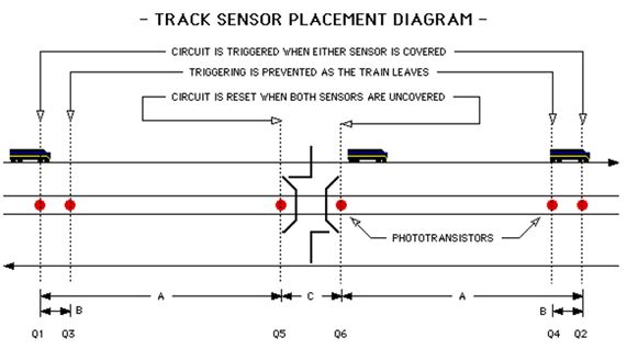
The second item I needed was an electronic circuit for detecting a train and controlling the gate operation. I had previously researched similar products and 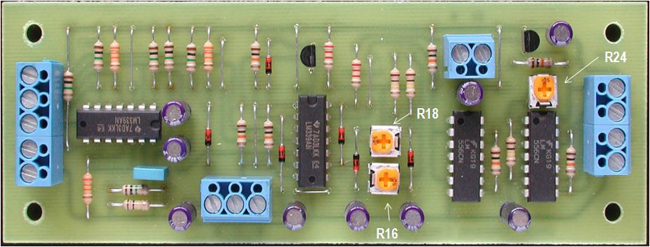 selected Rob
Paisley [5] as my preferred supplier. He provides wiring diagrams on
his web page; printed circuit boards, parts, kits, and fully wired
units are available. Rob's controller uses six visible and infrared
light sensitive phototransistors to detect a train and control the
circuit. I use it with ambient lighting. selected Rob
Paisley [5] as my preferred supplier. He provides wiring diagrams on
his web page; printed circuit boards, parts, kits, and fully wired
units are available. Rob's controller uses six visible and infrared
light sensitive phototransistors to detect a train and control the
circuit. I use it with ambient lighting. There are many sources of controllers. Dallee Electronics [6], offers a current sensing controller. Logic Rail Technologies [7] uses photocells with an option for infrared (IR). You select the number of IR sensors to include with Azatrax [8] controllers. Google will help you find more. Rob's circuit automatically controls railway grade crossing signals and gates in a prototypical manner, as do most of the others. The circuit has time delays that stagger the activation of the signal lights and lowering of the gates so that they operate as would be seen at a typical grade crossing when a train arrives or departs. The delay times are adjustable for both arriving and departing trains. The circuit is designed to directly control crossing gates that are powered by stall-motor type switch machine drivers. |
|||
I
bought the wired controller configured for flashing crossing signals
and gates. When a train enters the protected section of track the
flashers operate for a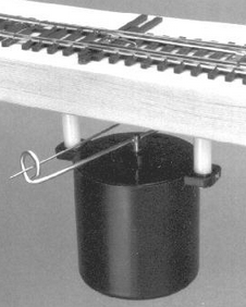 set time before the
crossing gates start to lower. After the train clears the grade
crossing, the signals will stay flashing until after the gates are up
fully. Both time delays can be adjusted. The controller has a dual
output signal driver allowing it to directly drive most signal wiring
configurations without added circuitry. set time before the
crossing gates start to lower. After the train clears the grade
crossing, the signals will stay flashing until after the gates are up
fully. Both time delays can be adjusted. The controller has a dual
output signal driver allowing it to directly drive most signal wiring
configurations without added circuitry.One circuit board can also be used to protect multiple tracks by using additional phototransistors. The circuit board has outputs to control a mechanical Grade Crossing Bell Ringer. The experience of my operating group is that frequent ringing of a bell gets annoying, so I opted to not install the bell. The final selection was the powered mechanism to move the gates. I rejected the Tortoise™ Slow Motion Switch Machine [9] as being difficult to adapt for a purpose other than the one for which it was designed. I also had reservations whether one Tortoise could activate both crossing gates. Several sources pointed to rotary switch machine motors as being more appropriate. I rejected the Micro-Mark® Switch Tender™ [10] based on several reviews that mentioned inadequate torque. I settled on the SwitchMaster™ from Builders In Scale [11] . |
|||
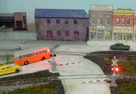
Operation
The grade
crossing flashers and gate operation sequence is:
|
|||
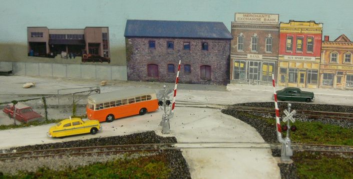
Installation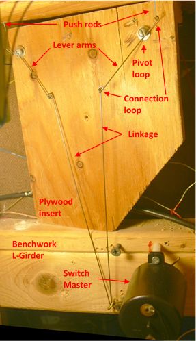 While I had several
grade crossings on the layout, none were on the main line, so I added a
T junction to an existing road; see While I had several
grade crossings on the layout, none were on the main line, so I added a
T junction to an existing road; see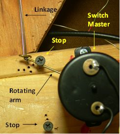 the illustrations at the
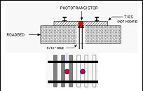
top of this article. My roads are made with molding plaster,
including between the tracks, and the flangeway is opened with a
hacksaw blade soon after the plaster sets. When I pored the road, I
included a base for each of the crossing gates. There was no obvious
way to mount the crossing gate base; I glued it to the plaster, which
provided a solid mount. Now let's look under the layout. the illustrations at the
top of this article. My roads are made with molding plaster,
including between the tracks, and the flangeway is opened with a
hacksaw blade soon after the plaster sets. When I pored the road, I
included a base for each of the crossing gates. There was no obvious
way to mount the crossing gate base; I glued it to the plaster, which
provided a solid mount. Now let's look under the layout. I inserted a piece of plywood just behind the two push rods that activate the gates. The picture to the left is a side view photograph taken under the layout.The plywood provided a flat surface to which I attached linkage. The plywood was cut to fit and attached with glue and screws. I made lever arms from piano wire. The lever arms have loops for pivot and at the ends. The lever arms are connected to the Switch Master by more piano wire linkages. The advantage of using piano wire is that it flexes if the travel is excessive. Screws are used to limit the rotation of the arm on the Switch Master (upper picture on right). 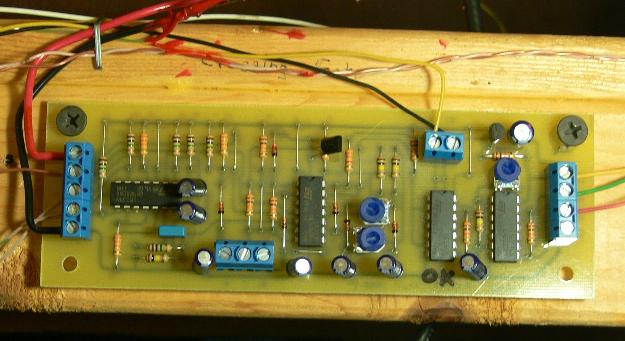 There's a certain amount of cut-and-fit experimentation in the length of the lever arms and linkage. If you look at the picture closely, you will see many holes where I tried locating the limit screws. The circuit board is screwed to the benchwork close by (lower right). |
| Notes | Major Parts |
|
[1] http://www.mthtrains.com/content/80-10001 [2] www.jimsmodeltrains.com/userguides/MTH8010001manual.pdf [3] http://www.tomarindustries.com/signals.htm [4] http://www.njinternational.com/hoscale1.htm [5] Email rpaisley4@cogeco.ca, web page http://home.cogeco.ca/~rpaisley4/CircuitIndex.html [6] http://www.dallee.com/GradeXing.htm [7] http://www.logicrailtech.com/ [8] http://www.azatrax.com/ [9] http://www.circuitron.com/index_files/Tortoise.htm [10] http://www.micromark.com/switch-tender-switch-machine,8394.html [11] http://www.builders-in-scale.com/bis/sm-mount.html [12] Several illustrations and descriptions courtesy of Rob Paisley. |
|
Return to ARE Home Return to more information
Revised 18January 2015